When I started using pixel art in game development, I assumed that it would easily work at any screen resolution, since modern screen resolutions are much higher than the native resolution of a pixel art game. However, I quickly came to realize that this is not the case – it’s actually quite tricky to get pixel art to look correct when scaling it up by an arbitrary amount. It works fine when it’s scaled by an integer multiple (2x, 3x, etc.), but there are issues when scaling by a non-integer multiple. This causes problems because the texture pixels (in other words, the pixels in the artwork, also known as texels) get scaled to fractional pixels on the screen. Because screens can’t display fractional pixels, the rendering has to either round to the nearest whole pixel, or it has to blend different texels into the same screen pixel. Choosing one of the two standard texture scaling modes will end up either making some of the pixels in the pixel art bigger than others or making them all blurry. Neither of these options look great, as seen in the example below.
| Distorted | Good | Blurry |
This led me to do a lot of googling to try to find a solution to the problem. Most resources I found claimed that you have to stick with scaling by integer multiples if you want it to look good, but I knew I’d played plenty of pixel art games that could scale to my screen size and look just fine. So I kept searching, and I finally came across a great solution using a shader (this is the “Good” version in the example image above), described at a blog called A Personal Wonderland. The author does a really nice job of explaining and illustrating the solution in a very mathematical way. It still took me a while to understand how it works, but I figured it out and was able to implement it in a Unity shader. Since it was so hard to find information about how to solve this problem, I decided to write this tutorial about scaling pixel art, explaining it in a way that makes more sense to my brain (and hopefully others’), and also giving an example of the solution in Unity.
Standard Scaling Approaches
The pixel art scaling shader is sort of a mix between the two standard scaling approaches: nearest neighbor filtering and bilinear filtering. Since fully understanding how the shader works depends on understanding these two filtering approaches, I’m going to first spend some time explaining them.
Nearest Neighbor Filtering
Nearest neighbor filtering is the simplest way to scale an image. With this method, you’re basically just taking the pixels from the texture and making them bigger to form the scaled image. This is done by giving a pixel in the scaled image the same color as the nearest texel.
The algorithm for performing nearest neighbor filtering is illustrated in the diagram below. First, the texture is taken, represented by a point at the center of each of the texels. This is then stretched to the size of the final scaled image and overlaid onto it. Each pixel in the scaled image is also represented by a point in its center. Next, for each point in the scaled image, the nearest point in the texture is found. The pixel represented by the scaled image point takes the same color as the texel represented by the texture point.
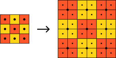
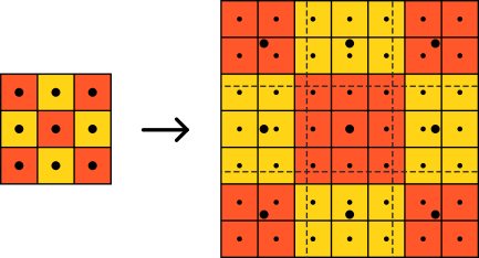
In the diagram above, the scaled image turns out perfectly, since it’s an integer multiple of the texture (in this case, 2x, since the texture is 3x3 and the scaled image is 6x6). However, if the scaled image is not an integer multiple of the texture, the final product won’t turn out quite right. See the diagram below for an example of this. Here, the texture is still 3x3, but the scaled image is 7x7. In the scaled image, you can see that some of the texels show up in different sizes and shapes, since it’s slightly larger than an integer multiple of the texture (2.333x).
Bilinear Filtering
With bilinear filtering, instead of making the texels bigger to form the scaled image, you’re blending the colors of the texels in the space between them. The term bilinear refers to the blending of colors in both the x and y directions.
As with nearest neighbor filtering, the bilinear filtering algorithm starts out by taking the set of points representing the texels, stretching it to the size of the scaled image, and overlaying it onto the set of points representing the pixels in the scaled image. Then, for each point in the scaled image, the four surrounding texel points are found. The colors of both pairs of texel points are first interpolated in one direction (either the x or y direction), so that the two new points are collinear with the point of the pixel being looked at. Finally, the color of the pixel is determined by interpolating the colors of the two new points at the location of the pixel point. See the diagram below for an illustration of this.
One other thing to note here is that some pixels around the edge might not be surrounded by four texels. The way this is generally dealt with is by creating imaginary texels past the edges of the texture with the same colors as edge texels.
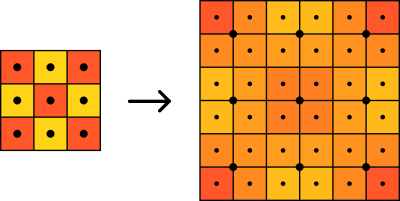
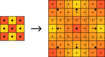
Here, I scaled the same 3x3 texture to 6x6, as I did with nearest neighbor filtering. However, as you can see, bilinear filtering produces a very blurry-looking result. This is not great for pixel art, obviously. However, there is one advantage to bilinear filtering, as seen in the diagram below (scaling the 3x3 texture to 7x7, like I did with nearest neighbor filtering). Even though the texture isn’t scaled to an integer multiple, it still looks uniform, rather than having the texels show up in different sizes and shapes.
Pixel Art Scaling Shader
Now that we’ve gone through how nearest neighbor and bilinear filtering work, we can move on to the pixel art scaling shader. As I mentioned earlier, this shader works by combining both nearest neighbor and bilinear filtering. For the most part, the shader uses nearest neighbor filtering, as this is best suited to pixel art. However, at the borders between texels, bilinear filtering is used. This is because, if a screen pixel is situated at one of these borders, it would contain parts of more than one texel. Remember, if we were to use nearest neighbor, that pixel would have to choose the color of only one of the texels, making the pixel art look distorted. The use of bilinear filtering at the borders blends the colors of the texels that share the same pixel, making it look more natural. This will not cause a noticeable blur, like pure bilinear filtering does, since we only use it at these borders. An example is shown in the diagram below.
![]()
Shader Code
Now that I’ve explained how the shader works conceptually, I’ll go through the code. Note that the code I’m showing is for Unity, but it should be relatively straightforward to translate it to something that works with another game engine or graphics library.
I’ll try to explain the code pretty clearly, but if you don’t have any experience with shaders, it might be a good idea to read up on them. When I was learning how to write shaders (specifically in Unity), I found this Cg Programming Wikibook to be an extremely helpful resource. Unity also has some helpful examples in their documentation.
Variables and Structs
To start, here are the variables and structs defined for the shader:
1
2
3
4
5
6
7
8
9
10
11
12
13
14
15
16
17
sampler2D _MainTex;
float4 _MainTex_TexelSize;
float texelsPerPixel;

struct vertexInput
{
  float4 vertex : POSITION;
  fixed4 color : COLOR;
  float2 textureCoords : TEXCOORD0;
};

struct vertexOutput
{
  float4 vertex : SV_POSITION;
  fixed4 color : COLOR;
  float2 textureCoords : TEXCOORD0;
};
_MainTex is the texture to draw, which is passed into the shader through the Properties block. _MainTex_TexelSize represents the size in texels of the main texture. This is a predefined property set up by Unity, as described here. texelsPerPixel is a value that we will set from a Unity script using Shader.SetGlobalFloat. As you can probably tell from the name, this variable represents the number of texels per screen pixel. We can calculate this value by dividing the screen width/height by the width/height of the game’s native resolution. If the aspect ratio of both the screen and the game’s native resolution are the same, you can use either the width or the height, but if the aspect ratios are different, you need to choose the dimension that doesn’t get letterboxed or pillarboxed.
The two structs defined here represent the input and output of the vertex shader. vertexInput contains the vertex position (in local space), the vertex color (which comes from the material color set in Unity), and the texture coordinates (which represent the x and y positions of the texture that match up with the vertex). vertexOutput contains the vertex position (in clip space), the vertex color, and the texture coordinates.
Vertex Shader
Moving on, let’s discuss the code for the vertex shader. The vertex shader is executed for each vertex of the object the shader is rendering. Here, we’re just getting the data in the format we’ll need it in for the fragment shader.
Note: The code for the vector shader and fragment shader is based on logic from A Personal Wonderland.
1
2
3
4
5
6
7
8
vertexOutput vertexShader(vertexInput input)
{
  vertexOutput output;
  output.vertex = mul(UNITY_MATRIX_MVP, input.vertex);
  output.textureCoords = input.textureCoords * _MainTex_TexelSize.zw;
  output.color = input.color;
  return output;
}
In line 4, we convert the vertex position from local space to clip space by multiplying it by the model view projection matrix. This is a pretty standard operation to perform in vertex shaders. In line 5, we convert the texture coordinates from the range [0, 1] to the range [0, texture size]. We do this because, in the fragment shader, we’ll need to know the texture coordinates in terms of texel position. Line 6 simply passes the input vertex color to the output.
Fragment Shader
Now to the fragment shader, which is executed for each pixel in order to calculate its color. This is where the main logic of the shader resides.
1
2
3
4
5
6
7
8
9
fixed4 fragmentShader(vertexOutput input) : SV_Target
{
  float2 locationWithinTexel = frac(input.textureCoords);
  float2 interpolationAmount = clamp(locationWithinTexel / texelsPerPixel, 0,
    .5) + clamp((locationWithinTexel - 1) / texelsPerPixel + .5, 0, .5);
  float2 finalTextureCoords = (floor(input.textureCoords) +
    interpolationAmount) / _MainTex_TexelSize.zw;
  return tex2D(_MainTex, finalTextureCoords) * input.color;
}
Here’s a simplified version of the logic we’re implementing in this function:
- For the current screen pixel, find its location in relation to the nearest texels (line 3).
- Using this information, determine how much (if at all) we need to interpolate between the colors of the nearest texels (lines 4-5). This is where the algorithm decides whether to use nearest neighbor or bilinear filtering for the current pixel. No interpolation means it’s using nearest neighbor filtering; interpolation means it’s using bilinear filtering.
- Given the interpolation amount, calculate and return the color of the pixel (lines 6-8).
Before we get into the details, I want to talk about how we go about interpolating the color values. We’ll actually set up the textures in Unity to use bilinear filtering. This will cause the graphics card to give bilinearly interpolated color values based on the texture coordinates given to it, and we’ll use our shader to pick the interpolated color values we want by changing the texture coordinates slightly. If we don’t want to interpolate colors for a pixel, we just choose the texture coordinates at the center of the texel. Otherwise, we choose the texture coordinates according to the amount of interpolation we want.
Okay, now that I’ve outlined the general logic, let’s go into more detail. Line 3 gets the fractional part of the texture coordinates. Remember that in the vertex shader, we converted the range of the texture coordinates from [0, 1] to [0, texture size], so our texture coordinates here have texels as the unit. So in getting the fractional part of the texture coordinates, we’re getting the fractional texel value where the screen pixel is located. As an example, if the texture coordinates were (34.4, 98.7), we’d be assigning the value (.4, .7) to locationWithinTexel. A value of (.5, .5) would mean that the center of the screen pixel lies directly on the center of the texel.
In lines 4-5, we’re using the locationWithinTexel value and the texelsPerPixel value to determine how much interpolation to use for this pixel. In most cases, we’ll end up choosing an interpolation amount of (.5, .5), which represents no interpolation, since it’s at the center of the texel. However, if the screen pixel is at a location where it partly lies within different texels, we’ll want to do some interpolation. An interpolation amount of (0, 0), (0, 1), (1, 0), or (1, 1) would represent the maximum amount of interpolation, since those points lie at the corners between texels. The first clamp function deals with pixels that lie on one side of the texel, and the second clamp function deals with pixels that lie on the other side of the texel. As an example, assume the scale we have is 2 screen pixels for each texel, so the texelsPerPixel value is .5. If the x-value of locationWithinTexel is 0, we should have the maximum amount of interpolation on the x-axis, since exactly half of the pixel would be on one texel and half would be on the other. On the other hand, if the x-value of locationWithinTexel is .25 (equal to half of texelsPerPixel), the left edge of the pixel would be lined up with the left edge of the texel. This means that there should be no interpolation on the x-axis, since the pixel is fully contained in the texel horizontally. As you can see, the first clamp function is designed to give a value of 0 when locationWithinTexel is 0 and to give a value of .5 when locationWithinTexel is at least half of texelsPerPixel. Anything in between is interpolated between 0 and .5. The second clamp function is designed similarly for the other side of the texel. If you want to see more details (and graphs) of this formula, please see the blog post at A Personal Wonderland.
In lines 6-7, we’re calculating the texture coordinates at which to retrieve the bilinearly filtered color from the graphics card (remember, this happens because we set the texture in Unity to use bilinear filtering). First, we take the non-fractional part of the input texture coordinates. If we were to sample the texture at this location, we would get a color with maximum interpolation between texels. Next, we add the value for interpolationAmount that we calculated in lines 4-5. If interpolationAmount is .5 on an axis, then the color will not be interpolated on that axis. If it’s 0 or 1, then it will have maximum interpolation, with 0 being on one side of the texel and 1 being on the other. Anything between those values will cause interpolation somewhere between the minimum and maximum. At this point, our texture coordinates are still in the range [0, texture size], but we need to get them back into the range [0, 1] before we can use them to grab the color. To do so, we simply divide by the texture width and height, or _MainTex_TexelSize.zw.
Finally, on line 8, we sample the texture at the calculated texture coordinates in order to get the color value we need. We also multiply this by the input color, which will have the effect of tinting the output with the material color set in Unity. If the material color is set to white, this will have no effect, since it will be multiplying by 1.
Complete Shader Code
Well, that wraps up the explanation of the pixel art scaling shader! That was a lot of information, but I hope you made it this far and understand how it all works. For reference, here is the complete shader code:
1
2
3
4
5
6
7
8
9
10
11
12
13
14
15
16
17
18
19
20
21
22
23
24
25
26
27
28
29
30
31
32
33
34
35
36
37
38
39
40
41
42
43
44
45
46
47
48
49
50
51
52
53
54
55
56
57
58
59
60
61
62
63
64
65
66
67
Shader "Custom/PixelArtShader"
{
  Properties
  {
    _MainTex("Texture", 2D) = "" {}
  }

  SubShader
  {
    Tags
    {
      "Queue" = "Transparent"
      "IgnoreProjector" = "True"
      "RenderType" = "Transparent"
    }

    ZWrite Off
    Blend SrcAlpha OneMinusSrcAlpha

    Pass
    {
      CGPROGRAM
      #pragma vertex vertexShader
      #pragma fragment fragmentShader

      sampler2D _MainTex;
      float4 _MainTex_TexelSize;
      float texelsPerPixel;

      struct vertexInput
      {
        float4 vertex : POSITION;
        fixed4 color : COLOR;
        float2 textureCoords : TEXCOORD0;
      };

      struct vertexOutput
      {
        float4 vertex : SV_POSITION;
        fixed4 color : COLOR;
        float2 textureCoords : TEXCOORD0;
      };

      vertexOutput vertexShader(vertexInput input)
      {
        vertexOutput output;
        output.vertex = mul(UNITY_MATRIX_MVP, input.vertex);
        output.textureCoords = input.textureCoords * _MainTex_TexelSize.zw;
        output.color = input.color;
        return output;
      }

      fixed4 fragmentShader(vertexOutput input) : SV_Target
      {
        float2 locationWithinTexel = frac(input.textureCoords);
        float2 interpolationAmount = clamp(locationWithinTexel / texelsPerPixel,
          0, .5) + clamp((locationWithinTexel - 1) / texelsPerPixel + .5, 0,
          .5);
        float2 finalTextureCoords = (floor(input.textureCoords) +
          interpolationAmount) / _MainTex_TexelSize.zw;
        return tex2D(_MainTex, finalTextureCoords) * input.color;
      }

      ENDCG
    }
  }
}